Monitoring Site Health with an Orb
Over a decade ago, I bought an Ambient Orb.
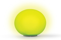
The orb is essentially a frosted glass sphere with LEDs in it that pulses different colors to indicate some kind of information — local weather, traffic, stock market trends, etc. It was designed to receive status updates over the air, although I’m not sure what type of radio it used. The company that made it offered a number of “channels” for different types of data. You would set your orb to a certain channel in their web interface, and they would periodically push status updates to it.
They also offered a “custom” channel where, for a modest monthly fee, you could send a request to their HTTP API and it would update the orb to a color and pulse speed of your choosing. I had always wanted to use this to make the orb display the build status at work (red would mean the master branch is broken), but there were two problems. First, the over the air updates were not real-time. Second, the company eventually stopped selling these devices, and their custom channel stopped working altogether. So the orb went back in its box, where it stayed for many years.
Ambient Orb
Fast forward to 2015. At a company hackathon, I saw a few engineers tinkering with Arduinos and LEDs, and it reminded me of the orb. I had never done any hardware hacking before, but I vaguely remembered that the orb had some kind of hardware development kit, so maybe it could be made to work with a direct connection instead of over the air?
After some research, I found that I had remembered correctly. The company used to offer an add-on board that exposes a serial interface, but of course they weren’t selling it anymore. Fortunately, I did find some documentation for the board that detailed the pinout and serial protocol, and with some more research I figured out how to use an Arduino Uno as a USB to serial TTL converter. By the end of the hackathon, I was able to set the color and pulse speed of the orb from my laptop!
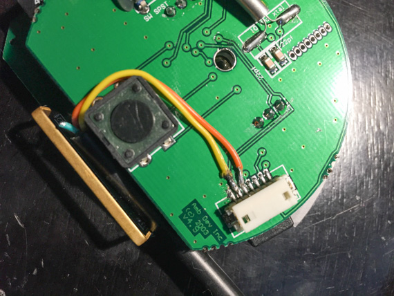
In my spare time the following week, I cleaned things up a bit. I bought a USB to serial TTL cable to take the place of the Arduino and soldered it to the orb’s circuit board.
I also wrote a ruby gem to autodetect the serial device and speak the orb’s custom protocol. Now I could write a ruby script monitor whatever I wanted, and it could push the appropriate color and pulse speed to the orb. Things were going great!
And then the blue LEDs failed. 😫
Although it could display any color, the orb was built with distinct red, green, and blue LEDs, covered by a sheet of translucent plastic to help diffuse the light and blend the colors. The firmware on the orb adjusted the brightness of the individual LEDs to create the desired color. But for some reason all the blue ones were either completely out or flickering dimly, so I could no longer represent colors with blue in them.
BlinkyTape Orb
I had come so far, I wasn’t about to give up. I didn’t know how to repair the orb’s electronics, but it might be possible to replace them.
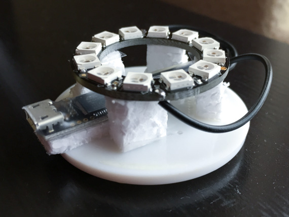
You can buy individually-addressable RGB LEDs (WS2812B) that come pre-soldered onto ring-shaped circuit boards. Adafruit calls them NeoPixel rings, and you can control them with an Arudino. I bought one. Over the next month I learned enough Arduino programming to emulate the Ambient Orb — talk to the Arudio over serial and the LEDs will pulse the specified color and speed.
My version has fewer color and speed choices, but I felt that adjacent settings on the original orb were indistinguishable anyway. By limiting myself to 6 colors and 4 pulse speeds, I was able to simplify the protocol to a single character. The firmware and a ruby gem to speak the new protocol are available on GitHub.
The Arduino Uno I was using for development was way too big to fit under the orb’s frosted glass sphere, but this was solvable. Blinkinlabs makes a LED light strip called a BlinkyTape, but sells their Arduino-compatible, ATMega32u4-based controller board separately. They also provide the source for their firmware and tell you how to load your own. I swapped in the BlinkyTape controller for the Arduino, and the whole package easily fit on the original base.
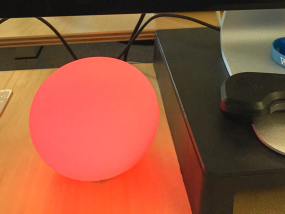
Here’s what it looks like with the frosted glass sphere back on. All the changes are on the inside, so it doesn’t look any different from the original orb.
Alternate Form Factors
Now that I knew how to build the electronics for an orb, I could build more of them! I kept the first orb at work, but I wanted one for my home office, too. Unfortunately, I only had a single frosted glass sphere from the original orb, so I experimented with a few different form factors for my home office orb: glass pebbles, frosted glass, and even no housing at all.
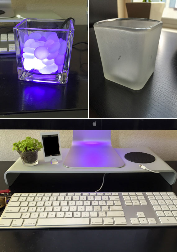
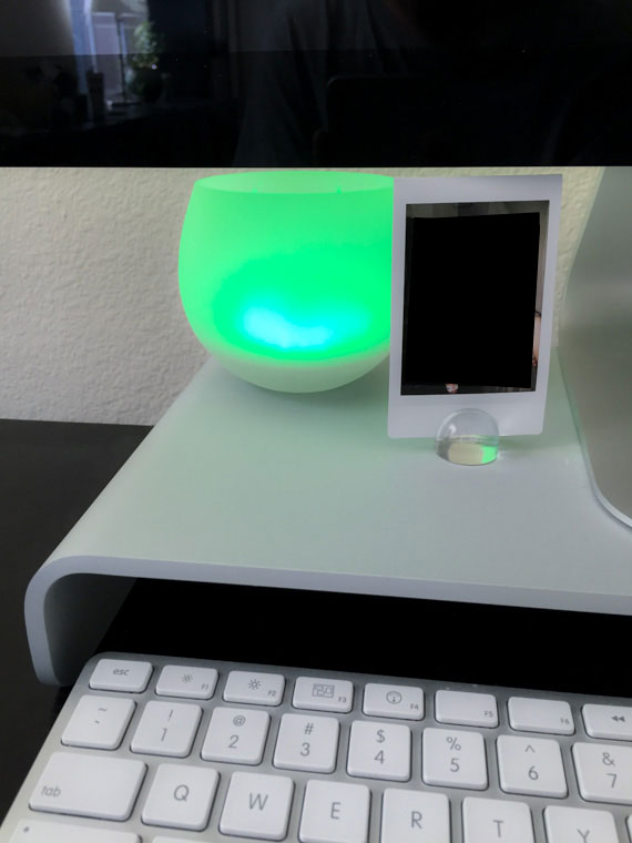
I liked the “no housing” option, where the LEDs are hidden behind my Thunderbolt Display and they simply illuminate the monitor’s base. But in the end I settled on a Harry Rocks Glass with frosted glass spray paint applied. It looked most like the original orb, and the frosted glass showcased the pulsing animation better than the “no housing” option.
ESP8266 Orb
Up until now, I had been relying on a ruby script running on my laptop to monitor things (more on this later) and push the appropriate color and pulse speed to the orb. This meant it only worked when my laptop was plugged in. A friend of mine at work had been following my progress on this project, but he took issue with the dependence on a computer. He wanted the orb to function independently over WiFi.
Enter the ESP8266, a cheap WiFi chip with a SDK that allows it to be programmed, meaning you don’t need a separate microcontroller. ESP8266 Arduino Core enables Arduino compatibility, and you can get modules such as the WeMos D1 mini with 4MB of flash and onboard USB for just a few dollars. Once ESP8266 support landed in FastLED, the LED control library I was using, all the pieces were in place to make the switch from the BlinkyTape controller to an ESP8266.
But the upgrade was not without challenges.
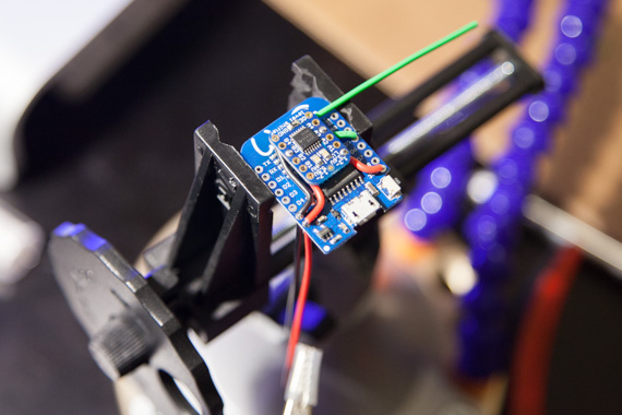
First off, the ES8266 operates at 3.3V, but the LEDs operate at 5V. While the D1 mini has a voltage regulator that allows it to accept 5V power from USB, the logic is still 3.3V, so I needed to add a level shifter to convert the 3.3V signals to 5V for the LEDs. Here it is, sitting on top of the D1 mini:
Another challenge was that the WiFi and TCP/IP libraries’ execution is interleaved with your code. From the ESP8266 Arduino Core documentation:
Remember that there is a lot of code that needs to run on the chip besides the sketch when WiFi is connected. WiFi and TCP/IP libraries get a chance to handle any pending events each time the
loop()function completes, OR whendelayis called. If you have a loop somewhere in your sketch that takes a lot of time (>50ms) without callingdelay, you might consider adding a call todelayfunction to keep the WiFi stack running smoothly.
The pulse animation code was a series of long loops, but I was calling delay to vary the speed of the animations, so this wasn’t an immediate problem. However, since the orb was independent now, it needed to fetch its own data over WiFi. A 1-character serial read is very fast, fast enough that you don’t notice it happening in the middle of an animation. So the serial code checks for an update at each step of the animation, and if an update is present, the current animation finishes up sooner and quickly transitions to the new animation specified by the update. An HTTP fetch is much slower, and you definitely notice the pause during an animation. To work around this, I broke up the fetch into two parts: sending the request and parsing the response. Both only run at the “top” of an animation, when the orb is at the brightest point in its pulse and the pause is least noticeable.
Overall, stability on the new platform was a problem for the first few months. Either the LEDs wouldn’t update properly, or the WiFi would drop out, or the whole thing would reset or freeze. Arduino Core 2.3.0 (released in June 2016) and FastLED 3.1.3 (September 2016) made things a lot better. Unfortunately, I started in April, and I was too inexperienced to know if the problem was on my end, or with the software or the hardware. It took a lot of trial and error to figure things out.
Beyond the initial challenges, there were a few features I wanted to add.
The original Ambient Orb had a button that cycled between 3 brightness levels. I moved this functionality to software in the BlinkyTape version — it had a serial command to change the brightness. In my home office, the medium setting was overwhelmingly bright when it was dark, but the low setting was too dim during the day. With the ESP8266 version, I integrated a light sensor (photoresistor) to automatically detect the ambient light in the room and adjust the brightness accordingly.
It took me a few tries to get this right in the firmware because I was treating a change in ambient light as distinct update (because that’s what it was in the BlinkyTape version) instead of something that is constantly sampled and compensated for in parallel to ongoing animations. I also struggled with the thresholds for a while. In the late afternoon the orb would flip back and forth between dim and medium. At first I tried fixing this by adding a holddown timer, but the real solution was to define both a high water mark and a low water mark.
Finally, I had been hard-coding the WiFi credentials in the source code. This meant that if the WiFi password ever changed, as it does at work, I would need to re-flash the orb to get it working again. To avoid this, I added a mode where if the orb can’t connect to WiFi for 30 seconds after booting, it becomes an access point with a captive portal. You can connect to it from your phone or computer, and the captive portal page lets you update the WiFi credentials the orb uses.
Hardware and Assembly
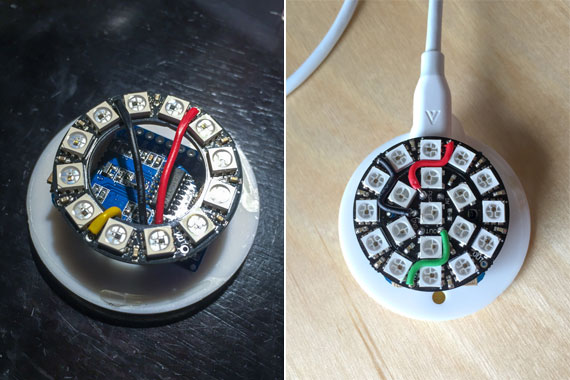
This is what the ESP8266 version of the original orb looks like on the inside with the frosted glass sphere removed. In the picture on the left, the BlinkyTape controller has simply been replaced with a D1 mini — I hadn’t figured out the level shifter situation yet, and despite a bit of flicker, the LEDs were mostly working without it. Later, I added the level shifter and a 7-LED “jewel” to increase the brightness. The glass sphere has a hole on the bottom, so it just sits right on top of this assembly. There’s a special cutout in the sphere for the cable.
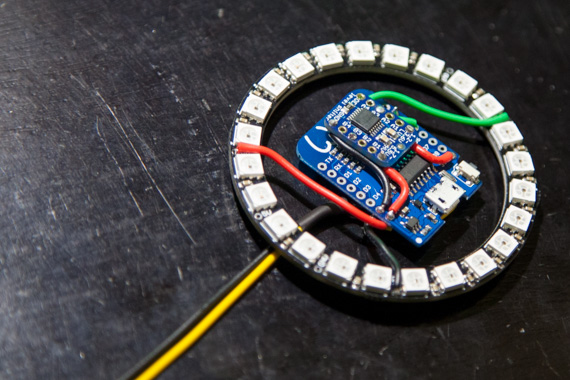
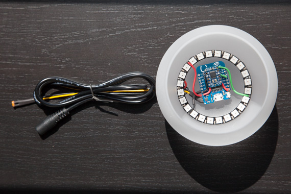
For the frosted whiskey glass orb, I used a 24-LED ring and put the D1 mini in the middle. The yellow and black wires lead to the light sensor.
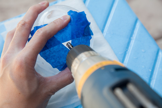
Since there’s no special cutout in the whiskey glass for the light sensor wires and power cable, I needed to drill a hole in the glass.
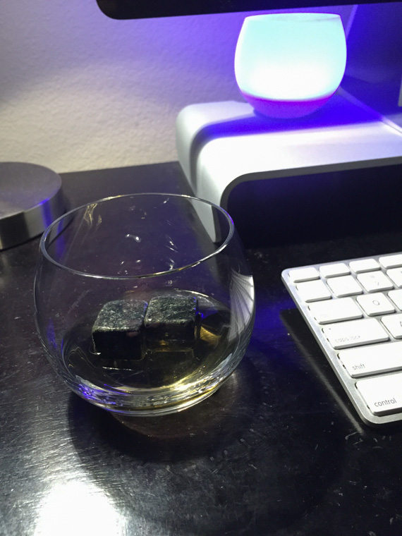
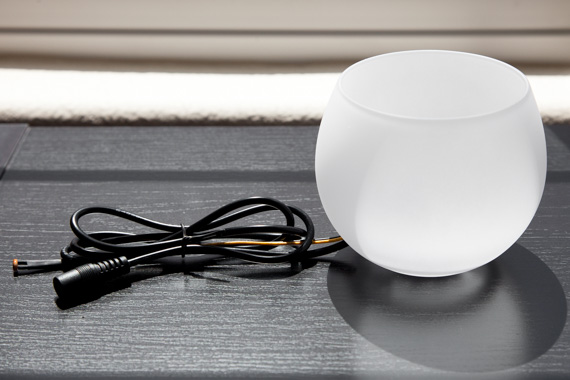
The finished product:
Monitoring Site Health
So what did I end up monitoring with these orbs? Back when I was still using ambient’s custom channel service, I was working for a company that sold on-premises software, so I just wanted to monitor the build. But by 2015, I was working for an Internet company, so monitoring our site’s health was far more interesting.
At the hackathon, in addition to hacking on the first iteration of the hardware, I also wrote a small service to aggregate data from our site monitoring systems, our internal deployment tool, and PagerDuty. The information is cached for 10 seconds and uploaded to S3 every time it changes.
The orbs poll the file in S3 every 10 seconds. I encoded the information as follows:
- Green - Situation Normal
- Blue - Deploy In Progress
- Purple - Deploys Locked
- Yellow - Elevated Error Rate
- Orange - Pager Duty
- Red - Site Down
At every level, the orb pulses faster. When it’s green, the pulse length is a few seconds, so it looks like it’s breathing. If it gets up to yellow, it’s pulsing about once a second, trying to get your attention. If it’s red, it pulses very quickly and is almost impossible to ignore.
While this started off as a fun project, over the years it’s proven to be quite effective as a “safety net” monitoring tool.
With our “real” monitoring tools, we try to keep the noise down to avoid alert fatigue. The bar is especially high for paging alerts, because no one wants to be woken up in the middle of the night only to find it’s a false positive. But with the orb, the cost of a false positive is low. If it flashes a warm color and I happen to be at my desk with a moment to spare, I can quickly glance at the “real” monitoring tools to see if further investigation is warranted. If it’s not, no big deal, I didn’t waste much time. I’m also not that worried about missing something important. If a serious issue arises and I’m not at my desk, or I’m busy with something else, the responsible parties should be alerted by our “real” monitoring tools.
Because the cost of a false positive is low, I can set the thresholds to be very sensitive. This allows me to notice errors and other phenomenon that would have otherwise flown under the radar of our “real” monitoring tools. For more serious issues, it also allows me to be alerted sooner, since the orb doesn’t wait for multiple failures over a given time interval before changing colors. As such, I’ve earned a reputation of omnipresence when it comes to site health.
I’ve since built a few more orbs for co-workers who are heavily involved in observability, availability and incident management. Having too many of them would be counter-productive because the cost of false positives would go up (lots of people wasting time following up on false positives), but having a few orbs increases the likelihood of something being followed up on even though it’s missed by our “real” monitoring tools. This, in turn, helps us improve our monitoring tools.